![]()
L298N Motor Driver Setup


Warning
This board is not compatible with TrackManager DC mode.
The L298N Motor board is the same H-Bridge on the Arduino Motor Shield. Here are the key differences:
It is in a much smaller form factor
It isn’t a shield so you have to jumper wires to connect it to your CS
It doesn’t have current sense, so you are going to have to use one of the solutions below
It stands vertically on the board with a big heat sink for better cooling
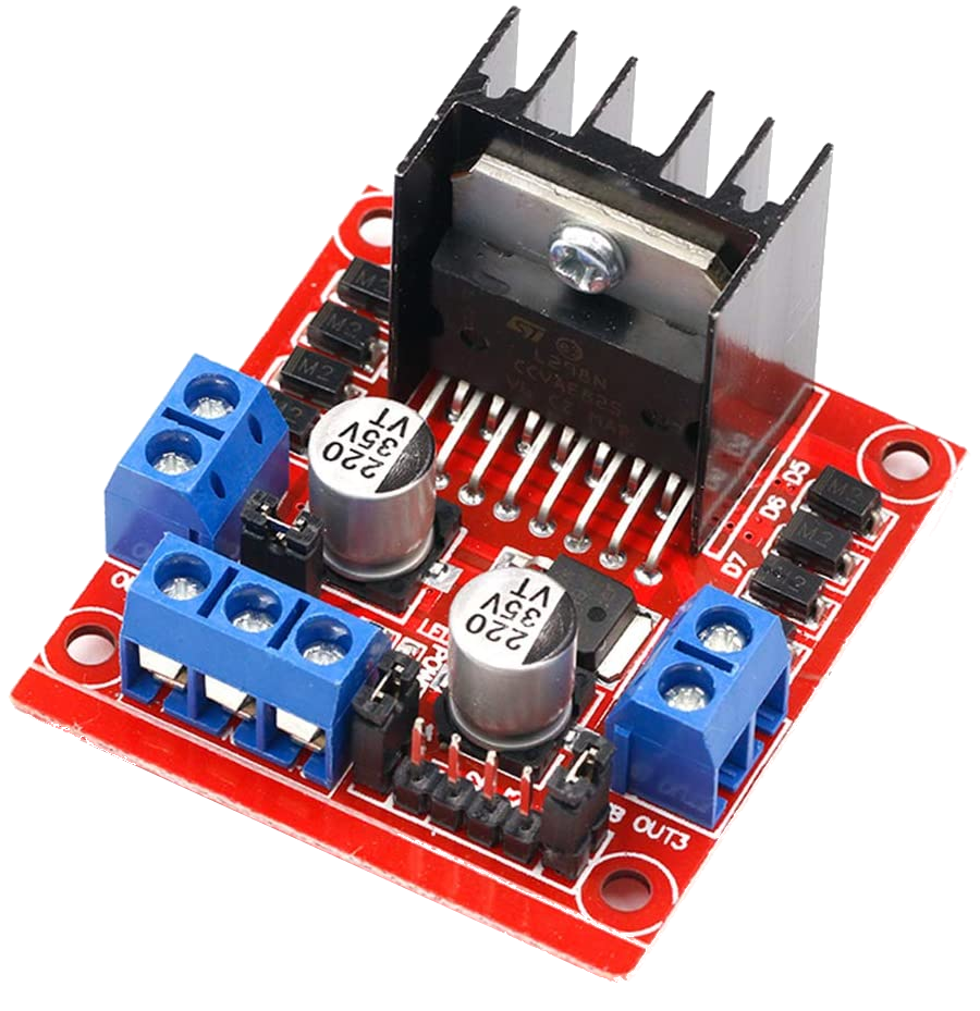
Figure 64 L298N Motor Board
When is the L298N a Good Option?
You may wonder why one would go through the trouble of using this board when the Arduino / Deek-Robot Motor Shield already has what we need and is a recommended option. The answer is you may want to use this board because:
You already have one in your parts box
They are dirt cheap
You are not using an Arduino for your Command Station and a shield is unwieldy
You want something smaller
You are going to use the L298N for programming and something with more current for MAIN
The disadvantage of this board:
It does not come with current sense. You will need to add it.
It does not have much more current output than the Arduino Motor Shield
L298N for MAIN and PROG with Current Sense
You will need to have currense sense in order to program locos on the programming (service) track. In addition, current sense is necessary to provide short-circuit detection for each track. There are two methods to add current sensing to this board, the first method requires cutting two leads on the IC and soldering in current sense resistors. The other method is to use an external current sense board to measure the current going into the board.
Method 1: Adding Current Sense Resistors
This is easier than it sounds and takes about 15 minutes. To do this yourself, you will need:
2 One Ohm, 3 Watt Power Resistors
small wire cutters
soldering iron and solder
18 Guage hookup wire
2 Male to Male Arduino jumper wires (dupont connectors)
Note
If you will only be using this board for the programming track and another board like the IBT_2 for your MAIN track, you only need one resistor and can follow the instructions for just the B side of the procedure.
You can either cut or lift legs on the L298 chip and insert resistors, or cut a trace on the back of the board and insert the resistors there.
Remove all jumpers, there are 3!
Choose how you will insert your current sense resistors from the following two options:
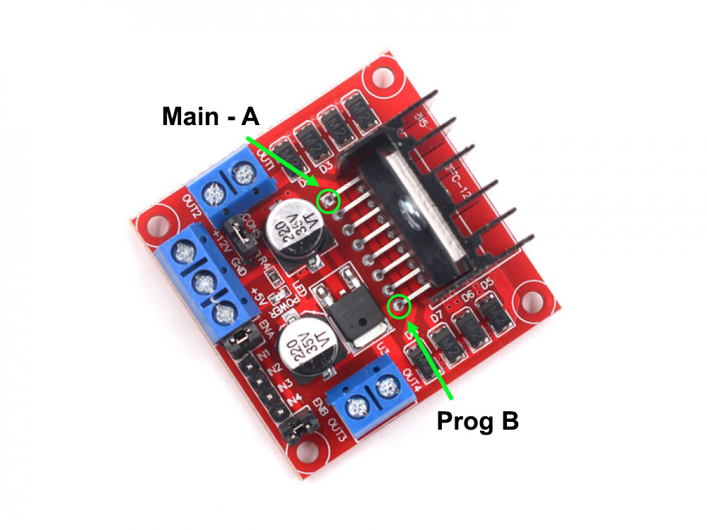
Figure 65 Lift or cut chip legs on front
or…
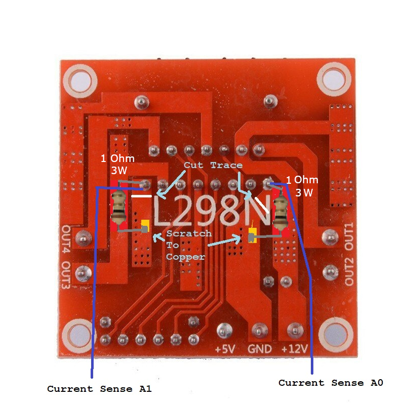
Figure 66 Cut traces and solder on back
Lifting Or Cutting Chip Legs Option
Remove all jumpers, there are 3!
Unsolder or cut the A and B current sense legs on the L298N chip at the green circles being careful to lift them out without breaking them. Pin 1 to the left is output Command Station
Output Afor MAIN. Pin 15 to the right is Command StationOutput Bfor PROG.Lift each leg and bend them carefully upward to provide space for a resistor.
Cut one wire lead of the 1 Ohm resistor short, but long enough that you can solder that end into the hole left by unsoldering the Command Station leg, about 1/4” (6mm). This connects one end of the resistor to ground. Solder the resistor from the bottom leaving air space for cooling. Repeat on the other side.
Solder the leg of the chip you unsoldered to the top of the resistor. You should be able to carefully bend the leg to meet the top resistor lead as the resistor stands vertically. You are basically inserting a resistor into the space where you cut the leg of the chip. Solder the wire fairly close to the end of the resistor. You may need a small piece of hookup wire to reach between the connections. Repeat on the other side. Do not trim the top resistor lead yet.
Measure a jumper wire long enough to connect from the top of resistor A and reach over push into pin A0 on the Arduino. Solder one end of the jumper to the top of resistor A above where you soldered the chip’s CS leg. Trim off any remaining resistor lead. Repeat for the resistor on side B making sure the male dupont end of the jumper can reach pin A1 on the Arduino.
If you haven’t already, plug the male end of the A jumper into pin A0 on the Arduino and the male end of the B jumper to pin A1 on the Arduino.
Configure the board in your Command Station in the next step.
Cutting Traces and Soldering on the Back Option
Using a razor blade or x-acto knife, carefully cut the ground pads where marked with white lines.
Using the blade, carefully scratch the conformal coating off the back of the circuit board where marked with yellow rectangles to expose the bare copper underneath. Be careful, you just want to scrape away the protective layer, you do not want to cut through the copper here.
Using an Ohmmeter, test for continuity between the newly exposed pads and the leg of the L298N chip on the other side that is soldered to the same pad. Make sure you have an open circuit (infinite resistance). If not, scrape a little more to widen the gap where you cut the trace, being careful not to cut too deep.
Trim the leads of your resistor to fit with one leg soldered to the solder joint of the current sense pin of the L298 and the other lead to the exposed ground pad you scraped clean as shown in the picture.
If you are using both sides of the L298 board for your MAIN and PROG tracks, repeat the process for the other side.
Configuring the Board in EX-CommandStation
You have two choices regarding how to wire and configure the L298N motor driver board to the command station. Unlike the Arduino Motor Shield, this board has separate direction inputs which is where we apply the DCC signal.
Your first choice, the easy way, is to create a new motor board definition that uses the proper pins. This requires you to edit the config.h file, cut and paste the motor board definition below, upload the sketch with the new settings, and connect wires from the L298N board to the correct pins on the Arduino. The only disadvantage to this method is that is uses an extra pin (though there are plenty of spare pins on a Mega), and it uses the standard accuracy waveform. Standard accuracy is fine for almost all cases, but you can read more on the High Accuracy Waveform Mode
Your second choice is to make a small inverter circuit (using 1 FET, IC, or transistor) to connect to the standard signal pin on the Command Station, and split it into two signals connect to the two pins on the L298N board. The advantage of this method is you use just one pin and get the high accuracy DCC waveform. The downside is that you have to solder together a circuit with 2 or 3 parts.
Using 2 signal pins (Avoids soldering a transistor inverter)
This method uses 2 pins on the Arduino for DCC signal pins and requires the following custom motor board definition. It uses the standard accuracy DCC waveform. The advantage of this method is that you don’t have to wire a transistor and 2 resistors to create an inverter circuit. The disadvantage is you use an extra pin for each track output and you get the standard accuracy waveform. See High Accuracy Waveform Mode to see if you really need it.
To wire the board, connect the pins according to the following diagram. A table is included as well. This pin usage, with all the pins lined up between boards, allows the use of a ribbon cable to make things a bit more neat:
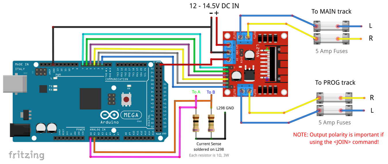
Figure 67 L298N 2 signal pin, 2 track wiring diagram
Arduino |
L298N |
|---|---|
7 (enable A) |
ENA |
6 (signal A1) |
IN1 |
5 (signal A2) |
IN2 |
A0 (CS MAIN) |
CS A |
2 (enable B) |
ENB |
4 (signal B1) |
IN3 |
3 (signal B2) |
IN4 |
A1 (CS PROG) |
CS B |
5V |
Vcc (+5V from Arduino) |
GND |
GND |
Once wired correctly, edit the config.h file and replace the following line:
#define MOTOR_SHIELD_TYPE STANDARD_MOTOR_SHIELD
with this:
#define MY_L298N_BOARD F("MY_L298N_BOARD"),\
   new MotorDriver(7, 6, 5, UNUSED_PIN, A0, 4.88, 2000, UNUSED_PIN), \
   new MotorDriver(2, 4, 3, UNUSED_PIN, A1, 4.88, 2000, UNUSED_PIN)

   #define MOTOR_SHIELD_TYPE MY_L298N_BOARD
Save the file and then upload the entire sketch into the Command Station using the Arduino IDE as explained in Installing Using the Arduino IDE
Using One Signal Pin With an Inverter circuit
This method uses 1 signal pin on the Arduino for each track and uses the standard motorboard definition. The advantage of this method is that it provides a slightly more accurate DCC waveform that might allow slightly better compatibility with really picky decoders, and you don’t have to change the default motor board definition. The disadvantage is that you have to solder a 1 transistor, 2 resistor (or inverter chip) to invert the signal into the 2 inputs on the L298 board.
Make the following Inverter circuit (You need 2 if you want MAIN and PROG):
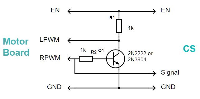
Figure 68 Transistor inverter circuit
Then wire the L298N to the Arduino with jumper wires according to the following table:
To wire the board, connect the pins as follows:
Arduino |
L298N |
|---|---|
3 (enable A) |
ENA |
12 (signal A1) |
IN4 |
Inverter A |
IN3 |
A0 (CS MAIN) |
CS A |
11 (enable B) |
ENB |
13 (signal B1) |
IN2 |
Inverter B |
IN1 |
A1 (CS PROG) |
CS B |
5V |
Vcc (+5V from Arduino) |
GND |
GND |
Once wired correctly, make sure your config.h file is configured for a STANDARD_MOTOR_SHIELD. If you have not already uploaded the CommandStation-EX sketch to your Command Station, you can make sure this line is in your config.h:
#define MOTOR_SHIELD_TYPE STANDARD_MOTOR_SHIELD
Save the file if you needed to add this line and then upload the entire sketch into the Command Station using the Arduino IDE as explained in Installing Using the Arduino IDE
Method 2: Using An External Current Sense Board
Coming Soon
Todo
LOW - Hardware - finish this page